PTFE (Polytetrafluoroethylene) is widely used in industrial sealing, chemical processing, electrical insulation and low-friction applications. Its excellent chemical resistance and low coefficient of friction make it a useful engineering material.
However, machining PTFE requires a different approach from machining metals or rigid engineering plastics. Its relatively low stiffness, high thermal expansion and tendency to deform under mechanical loading can affect dimensional accuracy and finished-part stability.
1. What Is PTFE CNC Machining?
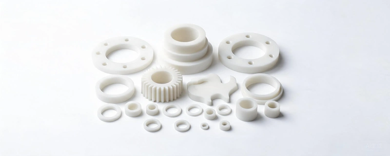
PTFE CNC machining is a subtractive manufacturing process used to produce custom components from PTFE sheets, rods and tubes. Computer-controlled turning, milling, drilling and other operations remove material to achieve the required geometry.
Compared with compression molding or die cutting, CNC machining offers greater flexibility for prototypes, small production batches, complex geometries and components made to engineering drawings.
Common CNC machined PTFE components include sealing rings, valve seats, bushings, sleeves, gaskets, insulators and custom chemical processing parts.
2. PTFE Material Grades for CNC Machining
PTFE is available in unfilled and modified formulations. The appropriate grade depends on chemical exposure, mechanical loading, friction, wear and dimensional requirements.
Virgin PTFE
Virgin PTFE contains no intentionally added reinforcing filler. It offers excellent chemical resistance, low friction and strong electrical insulation characteristics. It is commonly considered for chemical seals, gaskets, insulation parts and components where material purity is important.
Glass-Filled PTFE
Glass fiber reinforcement can improve stiffness, compressive behavior and wear characteristics compared with unfilled PTFE. The effect depends on the filler content and formulation. Chemical compatibility should be checked for the specific application.
Carbon-Filled PTFE
Carbon-filled formulations are used in selected applications where improved wear behavior, mechanical support or thermal conductivity is required. Their electrical properties differ from virgin PTFE, so they should not automatically be selected for electrical insulation.
Graphite-Filled PTFE
Graphite can modify friction and wear behavior in certain sliding applications. Performance depends on the graphite content, other ingredients and operating conditions.
Bronze-Filled PTFE
Bronze-filled PTFE is used in some mechanical and wear-related applications. It can offer improved mechanical support, but the metallic filler may affect chemical compatibility and electrical insulation.
3. PTFE CNC Machining Processes
CNC Turning
CNC turning is commonly used to produce round PTFE components such as sealing rings, bushings, sleeves, valve seats and cylindrical spacers. Proper workpiece support and controlled clamping help reduce deformation during machining.
CNC Milling
CNC milling is suitable for flat, shaped and more complex components, including custom gaskets, mounting parts and machined profiles. Tool selection, chip evacuation and workholding should be considered according to the geometry.
Drilling and Boring
Drilled holes and internal bores require attention to tool sharpness, heat generation and chip removal. Deep holes may require additional process planning to maintain dimensional consistency.
Threading and Finishing
Threaded PTFE components need suitable thread geometry and careful machining because PTFE is relatively soft and can deform under assembly loads. Surface requirements should be defined according to the sealing or mechanical function of the part.
4. Common Challenges in PTFE Machining
Low Stiffness and Deformation
PTFE is softer and less rigid than many engineering plastics. Excessive clamping pressure or cutting force can deform the workpiece, causing dimensional differences after the component is released.
High Thermal Expansion
PTFE has a relatively high coefficient of thermal expansion. Temperature changes during machining, storage and inspection can affect measured dimensions. Stable environmental conditions are particularly important for parts with demanding dimensional requirements.
Internal Stress and Dimensional Changes
Material processing history, stock dimensions and machining allowance can influence residual stress and dimensional behavior. For some components, staged machining and intermediate stabilization may help improve dimensional consistency.
Chip Removal
PTFE can produce soft, flexible chips during machining. Chip accumulation may interfere with cutting and surface finish. Appropriate chip evacuation and regular inspection of the cutting area are important.
Workholding and Support
Thin-wall parts and long components may require additional support. Clamping methods should hold the workpiece securely without introducing excessive deformation.
5. PTFE CNC Machining Tolerances
Dimensional tolerances for PTFE components should be evaluated according to the part's size, geometry, material grade and intended operating conditions. A tolerance suitable for a small spacer may not be practical for a large, thin-walled sealing component.
Several factors influence achievable dimensional accuracy:
- Part dimensions: Larger components may be more sensitive to thermal expansion and dimensional changes.
- Material grade: Virgin and filled PTFE grades can behave differently during machining.
- Geometry: Thin walls, long sections and deep features can increase deformation risks.
- Clamping: Excessive holding pressure may distort the workpiece.
- Temperature: Machining and inspection temperatures can influence measurements.
- Measurement method: Contact pressure and measurement technique should be suitable for a soft material.
For critical dimensions, specify the tolerance directly on the engineering drawing. It is also useful to identify reference dimensions, sealing surfaces, inspection requirements and the temperature at which dimensional acceptance is required.
6. PTFE CNC Part Design Guidelines
Maintain Practical Wall Thickness
Very thin sections can be difficult to hold and machine without deformation. Where possible, use practical and reasonably uniform wall thicknesses to simplify machining and improve dimensional stability.
Use Appropriate Internal Corner Radii
Internal corner radii can reduce sharp geometric transitions and make machining easier. Select a radius that is compatible with the component's function and the available cutting tools.
Consider Deep Holes and Long Features
Deep holes and long, slender features may require additional machining stages, workpiece support and chip-removal planning. Their dimensional requirements should be reviewed before production.
Design Threads for the Material
PTFE threads can deform under excessive tightening loads. Consider the assembly method, thread engagement, operating load and whether a metal insert or alternative connection design is more suitable.
Define Functional Surfaces
For sealing and sliding components, identify the surfaces that directly affect performance. This helps distinguish critical dimensions from non-critical features and avoids unnecessary tolerance requirements.
7. How to Machine PTFE Seals and Bushings
PTFE is frequently used for sealing and sliding components because of its chemical resistance and low-friction characteristics. However, the correct design depends on the application.
- Static seals: Consider compression, surface finish, sealing geometry and long-term creep.
- Dynamic seals: Evaluate speed, contact pressure, lubrication, mating surface and operating temperature.
- Bushings: Consider load, sliding speed, clearance, wear and the selected PTFE formulation.
- Valve seats: Review media compatibility, pressure, temperature and sealing requirements.
- Gaskets: Consider flange design, bolt loading, chemical exposure and long-term compression behavior.
PTFE is not automatically suitable for every high-load or high-pressure application. The complete operating conditions and component design must be evaluated before selecting the material.
8. PTFE CNC Machining vs. Compression Molding
CNC machining and compression molding serve different production needs. CNC machining removes material from stock shapes, while compression molding forms components using a mold and a controlled production process.
| Consideration | CNC Machining | Compression Molding |
|---|---|---|
| Tooling | Does not require a dedicated molding mold for each part geometry. | Requires suitable mold tooling. |
| Prototypes | Often practical for prototypes and small batches. | Tooling investment may be less attractive for one-off parts. |
| Complex geometry | Suitable for many custom shapes and machined features. | Geometry depends on mold design and process limitations. |
| Material usage | Material is removed during machining, creating offcuts and chips. | Material usage depends on molding design and process. |
| Production quantity | Useful when flexibility and low tooling investment matter. | May become attractive for repeat production with suitable tooling. |
The more economical method depends on part geometry, quantity, tooling investment, material utilization, machining time and production requirements. There is no universal quantity threshold for choosing one process over the other.
9. PTFE Machining vs. PEEK Machining
PTFE and PEEK are both used for demanding industrial applications, but their mechanical behavior and typical applications are different.
| Property | PTFE | PEEK |
|---|---|---|
| Mechanical stiffness | Relatively low | Significantly higher |
| Friction | Very low | Low for an engineering thermoplastic |
| Chemical resistance | Excellent against many chemicals | Excellent against many chemicals, but compatibility is application-dependent |
| Dimensional behavior | High thermal expansion and greater deformation tendency | Generally better dimensional rigidity |
| Typical applications | Seals, gaskets, valve seats and low-friction components | Structural parts, precision components, bearings and high-temperature applications |
PEEK is often considered when higher stiffness and mechanical strength are needed. PTFE is often selected when very low friction and broad chemical resistance are priorities. The final choice should be based on the actual working environment, not on a universal material ranking.
Learn more about our PEEK engineering plastics and PEEK CNC machining guide.
10. How to Request Custom PTFE Machined Parts
To evaluate a custom PTFE machining project, buyers should provide as much of the following information as possible:
- 2D engineering drawings with dimensions and tolerances.
- 3D CAD files, if available.
- Required material grade: virgin PTFE or a specified filled grade.
- Required dimensions and surface finish.
- Operating temperature and chemical environment.
- Static or dynamic working conditions.
- Expected quantity and order frequency.
- Inspection and documentation requirements.
Providing the application details helps evaluate the material selection, component geometry and manufacturing requirements. If the exact PTFE grade is not known, describe the working conditions so that the material options can be reviewed.
11. Frequently Asked Questions
Is PTFE suitable for CNC machining?
Yes. PTFE can be machined into custom components using CNC turning, milling, drilling and other processes. Its softness and thermal expansion require suitable workholding, heat control and dimensional inspection.
Can PTFE be machined to tight tolerances?
Tight tolerances may be possible for selected components, but achievable accuracy depends on size, geometry, material grade, machining conditions and inspection temperature. Each drawing should be reviewed individually.
What is the difference between virgin and filled PTFE?
Virgin PTFE contains no intentionally added reinforcing filler. Filled PTFE incorporates materials such as glass fiber, carbon, graphite or bronze to modify selected mechanical, friction or wear properties. The best choice depends on the application.
Can PTFE be used for seals and bushings?
Yes. PTFE is used for various sealing and sliding components. However, load, speed, pressure, temperature, mating surfaces, clearance and material formulation must be considered.
Is CNC machining better than molding for PTFE parts?
Neither process is universally better. CNC machining is useful for prototypes, custom geometry and smaller batches, while compression molding may be suitable for repeat production. Tooling, quantity, geometry and total manufacturing cost should be compared.
What information is needed for a PTFE machining quotation?
Ideally, provide a 2D drawing, a 3D model if available, material grade, quantity, tolerances and application details. These details help evaluate the project more accurately.
12. PTFE CNC Machining Supplier – Teda Plastics
Teda Plastics Co., Ltd. supplies engineering plastic materials and supports inquiries for custom plastic components based on customer requirements.
Our PTFE product range includes virgin and selected filled PTFE material options in stock shapes. Customers can contact us with their material requirements, dimensions or engineering drawings for project evaluation.
Whether you are sourcing PTFE stock material or evaluating a custom-machined component, providing the application details and technical requirements is the best starting point.
Send your 2D drawings, 3D CAD files or material specifications to discuss your requirements and request a quotation.
Email: info@tedaplastics.com
WhatsApp: +86 186 5333 9873
Request a Quote