Introduction: Why PEEK CNC Machining Requires Special Attention
PEEK (Polyetheretherketone) is a high-performance semi-crystalline thermoplastic known for its mechanical strength, chemical resistance and high-temperature capability. It can be machined using conventional CNC equipment, but its thermal behavior, elastic recovery and residual stresses require careful process control.
Compared with machining metal, producing accurate PEEK components involves different considerations. Heat buildup, workholding pressure, material grade and machining sequence can all affect final dimensions and part stability.
This guide explains the main considerations for successful PEEK CNC machining, from material selection and tool choice to tolerances and component design.
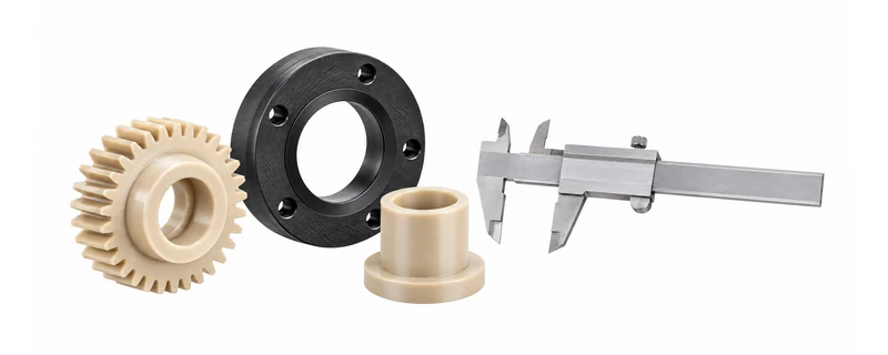
What Is CNC Machined PEEK?
CNC machined PEEK parts are manufactured by removing material from PEEK semi-finished stock shapes, such as sheets, rods and tubes. Computer-controlled milling, turning, drilling and other machining operations are used to produce components according to engineering drawings.
CNC machining is particularly useful for prototypes, customized components, complex geometries and low-to-medium production volumes. It avoids the need for dedicated injection molds and allows design changes to be made more easily.
The final properties of a machined component depend on the PEEK grade, stock manufacturing process, material condition and machining method. CNC machining does not automatically make a component stronger than an injection-molded part; the appropriate process depends on the application and design.
PEEK CNC Machining Processes
CNC Turning
CNC turning is suitable for cylindrical PEEK components such as bushings, sleeves, rollers, seals and shafts. Accurate workholding and controlled cutting conditions help maintain concentricity and dimensional consistency.
CNC Milling
CNC milling is used to manufacture flat components, housings, pockets, slots, mounting features and complex profiles. Thin sections and deep pockets require particular attention because cutting forces can cause deflection.
Drilling and Threading
Drilling and threading require sharp tools, suitable feed rates and effective chip evacuation. Deep holes may need peck drilling or other controlled drilling strategies to prevent chip accumulation and excessive heat.
Finishing and Secondary Operations
Depending on the drawing requirements, secondary operations may include deburring, edge finishing, precision re-machining and dimensional inspection. Annealing may also be considered as part of the machining process when residual stress could affect dimensional stability.
Critical Factors Affecting PEEK Machining
1. Material Grade Selection
Material selection has a direct influence on machining behavior and finished-part performance.
- Virgin PEEK: An unreinforced grade suitable for applications requiring a balance of strength, toughness and chemical resistance.
- CF30 PEEK: Contains approximately 30% carbon fiber reinforcement. It generally offers higher stiffness and improved dimensional stability in suitable designs, but its abrasive nature increases tool wear.
- GF30 PEEK: Contains approximately 30% glass fiber reinforcement. It provides increased stiffness in many applications and is also abrasive during machining.
Carbon-fiber- and glass-fiber-reinforced grades require appropriate wear-resistant cutting tools and process settings. Solid carbide tooling is commonly considered, while diamond tooling may be suitable for certain high-volume or specialized applications. Tool selection should be based on the material grade, cutting operation and required surface finish.
2. Internal Stress and Stress Relief Annealing
PEEK semi-finished stock can contain residual stresses introduced during extrusion, compression molding or cooling. When material is removed unevenly, these stresses may contribute to warping, dimensional movement or cracking.
Stress relief annealing may help improve dimensional stability, particularly for thick components, parts with substantial material removal or components with tight dimensional requirements.
However, annealing is not automatically required for every PEEK part. The decision depends on the stock manufacturing process, material grade, part geometry, machining allowance and final application. The annealing temperature and cycle must follow the material manufacturer's recommendations.
3. Heat Control and Cooling Methods
PEEK has relatively low thermal conductivity compared with metals. Heat generated during cutting can accumulate around the tool and workpiece, potentially affecting surface quality and dimensional accuracy.
Depending on the operation, cooling and chip-removal methods may include compressed air, suitable mist systems or compatible liquid coolants. There is no single cooling method that is best for every PEEK machining operation.
The main objectives are to prevent excessive localized heating, remove chips efficiently and maintain a stable machining environment. Coolant compatibility and cleanliness should also be considered for applications with specific contamination requirements.
4. Cutting Tools and Machining Parameters
Sharp cutting edges help reduce cutting forces, friction and heat generation. Tool geometry, rake angle, clearance angle and edge condition should be selected according to the PEEK grade and machining operation.
Reinforced PEEK grades can cause faster tool wear than unfilled PEEK. Worn tools may lead to rough surfaces, increased heat and inconsistent dimensions.
Cutting speed, feed rate and depth of cut should be established through machining trials and adjusted according to the machine, tool material, workpiece geometry and required finish. A parameter suitable for one PEEK grade or part design may not be suitable for another.
5. Workholding and Clamping
PEEK is less rigid than metal, so excessive clamping pressure can deform the workpiece. A component may appear dimensionally correct while clamped but move after it is released.
Proper fixture design, distributed clamping pressure and suitable support points help reduce distortion. Thin-wall components and long, slender parts often require additional support during machining.
PEEK CNC Machining Tolerances
Achievable PEEK machining tolerances depend on the component's size, geometry, material grade, stock condition, machining sequence and inspection environment.
A tolerance of ±0.01 mm may be achievable for certain small, rigid and well-controlled features. However, it should not be treated as a universal tolerance for every PEEK component.
Larger components, thin walls, long dimensions and asymmetric designs are more sensitive to thermal expansion, residual stress and workholding distortion. The difference between inspection temperature and actual operating temperature may also affect dimensional performance.
For critical dimensions, it is important to identify the required tolerance on the drawing and discuss feasibility with the machining supplier before production.
What Should Be Considered When Specifying Tolerances?
- Overall component size and dimensional proportions.
- Material grade and whether it is reinforced.
- Wall thickness and structural rigidity.
- Flatness, parallelism, concentricity and positional requirements.
- Operating temperature and environmental conditions.
- Measurement method and inspection temperature.
PEEK CNC Part Design Guidelines
Maintain Practical Wall Thickness
Very thin walls are more likely to deflect under cutting forces and clamping pressure. Where possible, maintain consistent wall thickness and avoid unnecessary thin sections. The appropriate minimum thickness depends on the component's size, geometry and machining setup.
Use Rounded Internal Corners
Sharp internal corners are difficult to machine with standard rotary cutting tools and can create stress concentration. Adding suitable internal radii can improve manufacturability and reduce machining time.
Consider Deep Holes Carefully
Deep holes require effective chip evacuation and appropriate drilling strategies. Hole depth, diameter, positional accuracy and surface finish should all be considered during design.
Design Thin-Wall Components with Support in Mind
Thin-wall PEEK parts may deform during machining or after unclamping. Where possible, add temporary machining support, improve fixture access or divide the machining process into controlled stages.
Specify Threads and Hole Features Clearly
Thread dimensions, engagement length, hole depth and edge conditions should be clearly defined on the drawing. Plastic threads should be designed with the expected assembly load and service conditions in mind.
CNC Machining vs. Injection Molding for PEEK
CNC machining and injection molding are two different manufacturing routes for PEEK components. The right choice depends on production volume, geometry, tooling investment, material utilization and dimensional requirements.
When CNC Machining Is Suitable
- Prototypes and product development.
- Customized components based on 2D drawings or 3D models.
- Low-to-medium production volumes.
- Parts requiring design flexibility without dedicated mold tooling.
- Components that can be manufactured efficiently from available stock shapes.
When Injection Molding May Be Suitable
- Repeated production of the same component in larger quantities.
- Complex shapes that are difficult or inefficient to machine.
- Projects where mold investment can be justified by production volume.
- Parts designed specifically for injection molding.
CNC machining generally avoids mold investment, while injection molding may reduce unit costs for suitable high-volume designs. However, the final comparison should include tooling, cycle time, material waste, secondary operations and quality requirements.
For more information about PEEK raw materials, see our PEEK granules guide.
Applications of CNC Machined PEEK Parts
PEEK components are used in demanding industrial environments where a combination of mechanical performance, chemical resistance and temperature capability is required. Typical applications include:
- Semiconductor equipment: Selected wafer-handling components, fixtures and precision parts.
- Aerospace: Lightweight brackets, bushings and other engineered components.
- Medical equipment: Selected instrument components manufactured from appropriate medical-grade materials.
- Oil and gas: Wear components, seal-related parts and selected downhole applications.
- Industrial machinery: Bearings, sleeves, gears, wear rings and customized mechanical components.
- Electrical and electronics: Insulating components and precision parts for demanding environments.
The suitability of a PEEK grade must be evaluated against the actual operating temperature, chemical exposure, mechanical load and any industry-specific requirements. Medical, food-contact and other regulated applications require confirmation of the exact material grade and relevant documentation.
How to Request a PEEK CNC Machining Quote
To receive a useful quotation, provide as much technical information as possible. A complete drawing package helps the supplier evaluate material selection, machining feasibility and inspection requirements.
- 2D drawing or 3D model: Include dimensions, tolerances and critical features.
- Material grade: Specify Virgin PEEK, CF30 PEEK, GF30 PEEK or another required grade.
- Quantity: State prototype quantity and expected production volume if known.
- Surface finish: Identify any critical surface requirements.
- Inspection requirements: Highlight critical dimensions and required inspection records.
- Application details: Explain operating temperature, load and chemical exposure where relevant.
If the exact PEEK grade is not yet decided, sharing the application and operating conditions can help identify suitable material options. You can also visit our PEEK material page for an overview of available PEEK forms.
Frequently Asked Questions About PEEK CNC Machining
Looking for a PEEK CNC Machining Supplier?
Teda Plastics Co., Ltd. supplies engineering plastic materials and provides CNC machining services for customized plastic components. We work with customer drawings and 3D models to evaluate machining requirements for PEEK parts.
Whether you need a prototype, a small production batch or a customized component, please send us your drawing and material requirements. We can review the specifications and discuss suitable material options, machining considerations and quotation details.
Request a Quote for Custom PEEK Parts
Send us your 2D drawing or 3D model. Tell us your material grade, quantity and critical dimensions for a quotation.
Request a Quote WhatsApp Us